
 +(91) 9867215033
 info@ujjwalengineers.com
 Maharashtra, Gujarat, India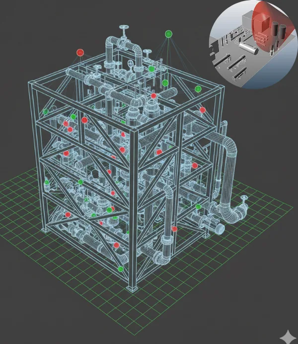
Why detector placement is not intuitive
Fire and gas detectors are still routinely placed by judgement - one per area, near the equipment that looks risky. The result is predictable: some zones are covered three times over and others not at all, and nobody knows which is which until there is a release.
3D fire and gas mapping replaces that judgement with a geometric model. The plant is built in 3D with its equipment, structures and obstructions, and detector coverage is computed against it.
Two coverage questions
- Geographic coverage - what fraction of the hazardous volume can be detected at all, regardless of where a leak starts. This exposes blind spots created by vessels and structures shadowing the detectors
- Scenario coverage - for the credible release cases, would the detectors actually see the cloud given its likely direction, size and the prevailing wind
Good geographic coverage with poor scenario coverage is common, and it is the more dangerous of the two failures.
Scope
- 3D model build from plot plans, isometrics or an existing model
- Assessment of existing detector layout, where one exists
- Coverage computation for point gas, open path, flame and smoke detection
- Optimised layout with detector count, position, height and orientation
- Voting logic and alarm threshold recommendations
- Coverage targets agreed against ISA TR84.00.07 performance-based method
Usually fewer detectors, better placed
Mapping is often assumed to mean more hardware. In practice it just as often reduces the count, because it identifies detectors doing nothing that another already covers - while closing the gaps that mattered.
Frequently asked questions
What coverage target should we set?
There is no universal figure. It is set from the risk of the area - a high-pressure gas compressor house warrants a higher target than a low-hazard utility area. Agreeing that target is the first step of the study.
Do you need an existing 3D model?
It helps and shortens the work, but is not required. We build the model from plot plans, equipment layouts and photographs where none exists.
Does this replace a HAZOP?
No. HAZOP identifies what can release and why. F&G mapping answers whether you would detect it if it did. They answer different questions.
How does it relate to CFD?
Mapping uses geometric coverage. Where dispersion behaviour in congested space is the question, CFD models the actual gas movement, and the two are often run together.





 As per MOEF & CC’s (Govt. of India) Office Memorandum F.
No. 22-34/2018-IA.III dated 9th August 2018 Self-Environmental Audit shall be conducted annually. Every
three years third party environmental Audit shall be carried out.
As per MOEF & CC’s (Govt. of India) Office Memorandum F.
No. 22-34/2018-IA.III dated 9th August 2018 Self-Environmental Audit shall be conducted annually. Every
three years third party environmental Audit shall be carried out.